The first clamp near a bend, valve or fitting controls local tube movement and helps keep component ports from carrying pipe weight. It should normally be closer than regular straight-run spacing.
Closer does not mean touching the component. Preserve a straight clamping surface, wrench access, removal space, hose movement and required thermal expansion.
Place the clamp close enough that the elbow, valve or fitting does not carry the unsupported tube weight or repeated bending, but leave enough straight length for assembly, wrench access, inspection and thermal movement. There is no single universal distance.
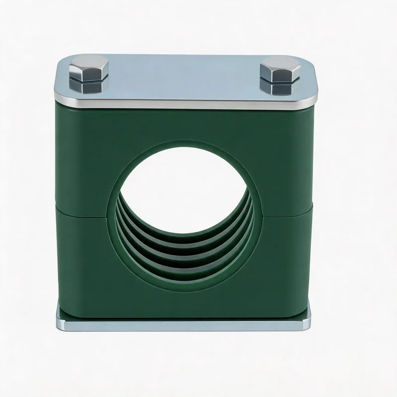
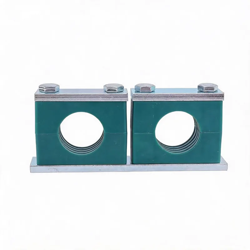
Related product photos
Typical use cases
- Clamp the straight tube, not the elbow radius or fitting body
- Prevent valves, manifolds and unions from becoming pipe supports
- Support heavy inline components independently when required
- Keep wrench, filter and hose removal envelopes clear
Placement by nearby component
| Nearby component | Preferred support approach | Keep clear | Common failure |
|---|---|---|---|
| Elbow or formed bend | Clamp the nearest practical straight section; review both legs when movement or mass is high. | Bend radius and forming transition | Clamping on an uneven bend or leaving a long cantilever. |
| Valve or actuator | Support adjacent tube and independently support heavy valve mass when needed. | Handle, actuator, bolts and removal path | Letting the valve or port carry tube and maintenance load. |
| Manifold or equipment port | Place a stiff support near the tube exit without transferring misalignment into the port. | Wrench access and connector removal | Using the port as the first structural support. |
| Union or threaded fitting | Support the tube so assembly torque and pipe weight do not bend the joint. | Tool swing and disconnection length | Placing the clamp where the joint cannot be serviced. |
| Heavy filter or cooler | Use independent support or supports on both sides where practical. | Element replacement and drain access | Suspending component weight from small tube connections. |
| Hose-to-tube transition | Support the rigid tube side and preserve the hose movement envelope. | Minimum bend radius and coupling access | Allowing hose motion to shake or twist the rigid tube. |
Apply regular straight-run spacing only after these local supports are established. Exact dimensions require actual geometry and project rules.
Why one fixed distance is misleading
A small elbow, a large actuated valve and a hose transition do not create the same load. Tube OD, wall, component mass, pulsation, orientation and bracket stiffness change the required location. Use the nearest practical straight section with service access as the starting principle, then verify it.
Support the load, not just the tube shape
A nearby clamp works only when its base and structure are stiff enough. Heavy valves, filters and coolers may need their own bracket. Check the complete load path through the clamp, base plate and machine frame.
Preserve assembly and maintenance access
Simulate bolt removal, wrench swing, union separation, filter withdrawal and hose coupling access before fixing the clamp. A clamp that blocks routine service often gets loosened or omitted during maintenance.
RFQ and layout data to send
Send tube OD and wall, component type and approximate mass, orientation, pressure and pulsation notes, available straight length, proposed clamp location, mounting surface and maintenance envelope. A marked photo or routing drawing is the fastest review method.
Frequently asked questions
Should a pipe clamp be installed directly against an elbow?
Not automatically. Support the straight tube close to the elbow, but keep enough straight length for the clamp body, tube forming tolerance, inspection and assembly. Do not force the clamp onto the bend radius.
Do heavy valves need clamps on both sides?
Often they need independent support or supports on both sides, especially when the valve mass, actuator, vibration or maintenance load would otherwise be carried by the tube and fittings. The valve manufacturer and project layout control the final arrangement.
Where should the clamp go at a hose-to-tube transition?
Support the rigid tube side near the transition while keeping the hose bend and movement envelope free. The hose must not pull, twist or repeatedly bend the rigid tube fitting.
Related WeiQue series


Recommended reading
References
These pages summarize public standard metadata and industry application information. They do not reproduce the paid DIN standard text.