
The practical rule: pipe clamps near fast-acting valves, reciprocating pumps and abrupt direction changes must be sized for transient surge, not the steady working pressure. When a valve closes faster than the pipe can accommodate the flow change, the Joukowsky relation gives a pressure rise of ρ·a·Δv — for water this is roughly 1 MPa (about 10 bar) for every 1 m/s of velocity stopped, arriving in milliseconds and reflecting back and forth along the run. The unbalanced force this puts on the pipe segment between two direction changes acts directly through the clamps into the structure, and it can be several times the force the same line sees in steady operation. Halve the normal clamp spacing within the surge-affected zone, place a clamp close to each side of a fast-acting valve and each elbow, and step up to heavy-series or cushioned clamps where the transient regime is severe.
This is one of the most common gaps between what an RFQ states and what the clamp actually has to survive. A buyer gives the working pressure — say 160 bar for a hydraulic line — and assumes that number sizes everything. But the working pressure is a static value; it says nothing about how fast valves close, whether the pump is reciprocating, or how long the straight runs between direction changes are, all of which set the transient force the supports must react. A line rated for 160 bar steady can see a momentary surge peak well above that, and the clamps — not the pipe wall — are what hold the line when it tries to jump.
Pipe clamps near fast valves, reciprocating pumps and direction changes must be sized for transient surge, not the static working pressure. Water hammer spikes pressure by ρ·a·Δv (about 10 bar per 1 m/s stopped in water), so halve spacing in the surge zone, anchor each side of valves and elbows, and step up to heavy-series or cushioned clamps.
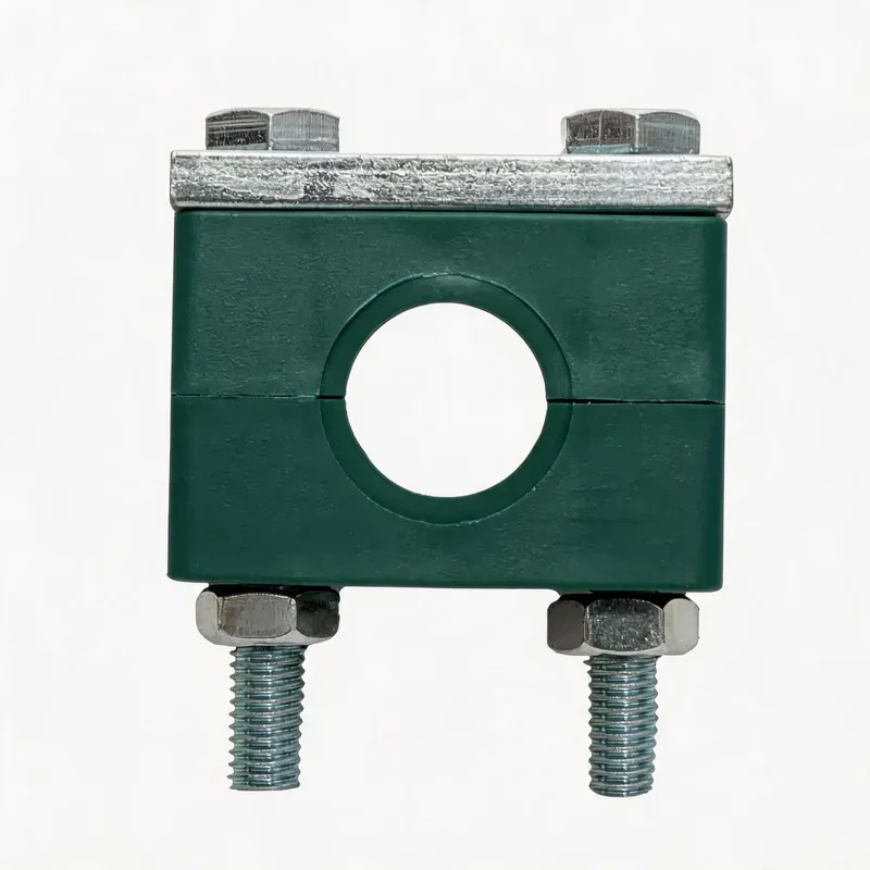
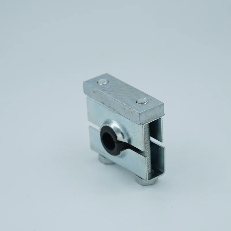
Mounting methods at a glance
Key points
- The Joukowsky equation ΔP = ρ·a·Δv sets the surge magnitude: for water (a ≈ 1000–1400 m/s) a 1 m/s velocity change gives roughly 10–14 bar of instantaneous pressure rise; in stiff pipe the wave speed and therefore the surge is higher.
- The support load comes from the unbalanced force on each pipe segment between direction changes: during the transient, F = ΔP × bore area acts on the elbow or cap, and the clamps on that leg must react it. A DN50 bore under a 30 bar surge sees an unbalanced force on the order of several kN — a dynamic pulse, not a steady pull.
- Piping design codes treat surge as an occasional load: supports near transient sources are sized for the momentary peak, not just the sustained pressure. Applying only the working-pressure figure to a support near a fast valve under-sizes it against the load case that actually governs.
- Surge is repeated, not a one-off: every valve cycle and pump stroke repeats the pulse, so the failure mode at under-supported points is fatigue — bolt loosening, insert wear and eventual clamp or fitting cracking — rather than a single overload. This is why cushioned clamps, which damp each impulse, earn their place on pulsating lines.
- Clamp layout is itself a mitigation: anchoring the pipe close to each side of valves and bends shortens the unsupported column and keeps the transient force from turning into visible pipe movement. It complements, but does not replace, hydraulic mitigation (slower valve closure, accumulators, surge vessels) designed by the system engineer.
Where surge concentrates and the clamp response
| Location | Why force concentrates | Clamp / spacing action |
|---|---|---|
| Fast-acting / solenoid valve | Rapid closure produces the full Joukowsky rise | Clamp each side of the valve; heavy series |
| Elbow, tee, direction change | Unbalanced surge force F = ΔP × bore area acts on the bend | Anchor clamp close to the fitting, both legs |
| Reciprocating pump discharge | Repeated pressure pulsation at pump frequency | Cushioned clamps; halved spacing within ~3 m |
| Long straight run before a valve | Longer column of fluid stores more momentum to arrest | Reduce span; verify clamp axial grip |
| Pump start/stop, check-valve slam | Sudden flow reversal drives a reverse surge | Anchor near the valve; review restraint direction |
Surge severity depends on how fast the velocity changes relative to the pipe period 2L/a (L = run length to the nearest reflection point, a = pressure wave speed). A closure faster than 2L/a produces the full Joukowsky pressure rise; slower closures produce proportionally less. When closure times are unknown, size the supports for the worst credible fast closure.
Why working pressure does not size a surge-loaded clamp
Working pressure is a static quantity: it describes the force balance when flow is steady, and in that state a correctly sized clamp of any series holds the pipe comfortably, because the pressure is contained by the pipe wall and the support only carries weight and thermal load. Water hammer changes the problem from static to dynamic. When a valve closes or a pump trips, the moving column of fluid cannot stop instantly; its momentum converts to a pressure spike governed by the Joukowsky relation, ΔP = ρ·a·Δv, where ρ is fluid density, a is the pressure-wave speed in that pipe, and Δv is the velocity change. The wave travels to the nearest boundary — an open tank, a larger header, a closed end — reflects, and returns, so the pipe between two reflection points is loaded, unloaded and reloaded on a timescale of milliseconds to tens of milliseconds. What the supports feel is the unbalanced force on each straight segment: while the wave is passing, the pressure at one end of a run differs from the other, and that difference acting on the bore area pushes the pipe axially. At a direction change the force does not cancel — it drives the elbow, and the clamps on the two legs must react a dynamic pulse that can be several times the steady thrust. This is why two lines with the same working pressure can need very different supports: the one with a fast solenoid valve and long straight approaches has a severe transient regime, and the one with slow manual valves and short runs barely surges at all.
How fast is "fast": closure time, wave speed and the 2L/a period
Whether a valve closure produces a severe surge or a mild one depends on how its closure time compares to the pipe period, 2L/a, where L is the distance from the valve to the nearest point where the wave can reflect and a is the wave speed. If the valve closes faster than 2L/a, the full Joukowsky pressure rise develops before any relief wave can return — this is "rapid" or "instantaneous" closure and it is the worst case. If the valve closes more slowly, the returning relief wave limits the peak, and the surge scales down roughly in proportion. Two design implications follow for clamp specification. First, wave speed is not a constant: it is highest in stiff steel pipe carrying stiff fluid (water, oil) and lower in flexible or thick-walled pipe and in fluids carrying entrained gas — which is why the same valve on a rigid hydraulic line surges harder than on a compliant one. Published research on transient flow shows that pipe-wall elasticity and fluid–structure interaction measurably change both the peak and its timing, so a real installation rarely reaches the textbook maximum, but it can come close on a stiff line. Second, the designer often does not know the exact closure time at the RFQ stage, especially for solenoid and check valves whose effective closure can be a few milliseconds. The safe engineering posture for the support supplier is to size the clamps near a fast valve for a credible rapid-closure surge rather than the working pressure, because under-supporting is a latent fatigue problem while modestly over-supporting a few clamp positions costs very little.
Where surge fails supports first — the industry pattern
Across hydraulic and process installations, the supports that fail first under surge are consistently the same handful of positions, and the reason is geometric rather than incidental. The clamp immediately downstream of a fast-acting or solenoid valve takes the direct hit of the pressure spike; the clamps on both legs of the first elbow after a pump or valve react the unbalanced turning force; and the supports on a long unsupported straight run leading into a valve carry the momentum of the longest fluid column. Reciprocating pump discharge lines are a category of their own, because the surge is not a rare event but a continuous pulsation at pump frequency, so the failure there is classic fatigue: bolts back off, cushioned inserts wear and harden, and eventually a clamp or a fitting cracks. The pattern is well enough established that mature piping specifications call out these positions explicitly — anchor clamps at direction changes, reduced spacing in the pump-adjacent zone, cushioned clamps on pulsating discharge — rather than leaving spacing to a single default table. The common thread in under-designed installations is that the surge regime was never described to whoever selected the supports: the pressure rating was passed on, the valve types and closure behaviour were not, and the clamp schedule was built for the static case. Naming the transient sources when the support scheme is set is what moves these positions from latent failure points to correctly specified anchors.
What to write in the RFQ for surge-exposed lines
A clamp schedule can only account for surge if the RFQ describes the transient regime, not just the working pressure. Four lines carry the information a support supplier actually needs. State the fluid and both pressures: the steady working pressure and the design surge or peak transient pressure if a hydraulic transient analysis exists — and if it does not, say so, so the worst-case assumption is explicit rather than hidden. State the valve and pump character: fast-acting or solenoid valves, check valves prone to slam, and reciprocating versus centrifugal pumps, because these set whether the line surges at all and how often. State the geometry that matters for support layout: the positions of fast valves and the major direction changes, and the length of any long straight runs approaching them, so anchor clamps and reduced spacing can be placed where the force concentrates rather than uniformly. And state whether the pulsation is continuous, as on a reciprocating pump discharge, so cushioned clamps can be proposed for fatigue duty rather than rigid clamps sized only for a single peak. WeiQue supplies DIN 3015 standard, heavy-series and cushioned clamps and can advise on spacing and anchor positions for surge-exposed lines; send the four lines with your isometric or line list and we will mark the positions that should step up to heavy or cushioned clamps and where spacing should be reduced, rather than pricing the whole run at one series.
Frequently asked questions
Does the working pressure tell me what clamp to use near a fast valve?
No. Working pressure is a static value; the load near a fast valve comes from the transient surge when flow stops. A line rated 160 bar steady can see a momentary peak well above that, and the clamps — not the pipe wall — hold the line when it tries to jump. Size supports near fast valves for the surge, and give the valve closure behaviour in the RFQ.
Where do pipe clamps fail first from water hammer?
Consistently at a few geometric positions: the clamp just downstream of a fast or solenoid valve, both legs of the first elbow after a pump or valve, and long unsupported straight runs into a valve. Reciprocating pump discharge lines fail by fatigue from continuous pulsation. Anchor clamps close to valves and bends, reduce spacing in these zones, and use cushioned clamps on pulsating discharge.
Do cushioned clamps help against water hammer?
Yes, on repeated pulsation. Surge is not a one-off — every valve cycle and pump stroke repeats the pulse, so the failure at under-supported points is fatigue: loosening, insert wear, eventual cracking. Cushioned clamps damp each impulse and suit pulsating lines. They complement, not replace, hydraulic mitigation (slower closure, accumulators) designed by the system engineer.
Related WeiQue series


Recommended reading
References
Further reading: the surge magnitude follows the Joukowsky/Allievi relation, and piping design codes (e.g. ASME B31) treat transient surge as an occasional load on supports. Open-access research below covers water hammer in oil-hydraulic pipe, dynamic pipe response and fluid–structure interaction, and surge mitigation.
- High-Speed Imaging of Water Hammer Cavitation in Oil–Hydraulic Pipe Flow — Fluids 7(3):102 (MDPI, open access)
- Dynamic Responses in a Pipe Surrounded by Compacted Soil Suffering from Water Hammer with Fluid–Structure–Soil Interactions — Water 16(18):2668 (MDPI, open access)
- Investigation of Water Hammer Protection in Water Supply Pipeline Systems Using an Intelligent Self-Controlled Surge Tank — Energies 11(6):1450 (MDPI, open access)